Pore workflow
Pore mode runs HOLE along a user-defined channel direction. Use it when the structure has one known through-pore or channel and the scientific question is how its cross-section changes along that path.
1. Prepare the system
Load a structure or trajectory in VMD. Before analysis:
- make each protein copy whole when it crosses periodic boundaries;
- align a mobile protein before comparing frames with one fixed
CPOINTandCVECT; - choose an atom selection that represents the pore wall;
- choose a radius file that covers every selected atom.
Choose atoms for the question being asked. A pore-wall selection is a useful starting point; include bound cofactors, ligands, ions, membrane, or solvent when they should contribute to the accessible geometry. Excluded atoms are invisible to HOLE, while including more atoms can change the profile and cost.
2. Define frames
The Frames field accepts:
| Syntax | Meaning |
|---|---|
now |
current VMD frame |
all |
every frame |
12 |
frame 12 |
0:100 |
frames 0 through 100 |
0:5:100 |
frames 0 through 100 with stride 5 |
Choose a stride that retains the changes you need to observe. Increase it only when skipped frames cannot change the conclusion.
3. Define CPOINT and CVECT
CPOINT is the initial point from which HOLE searches for the largest sphere in
the first plane. It should lie inside the intended pore. Enter x y z, use a
selection's centre of geometry (COG), or use VMD's centre of rotation
(COR). Enable Show cues to display the point in the VMD view.
CVECT is the channel direction. Enter a vector, or open the ⌖ dialog,
whose CVECT page can also infer a direction with Guess, use the Z axis, or
compute it from two points given as coordinates, VMD selections, or labelled
atoms. HOLE searches in planes normal to the resulting vector. A poor direction can produce a valid
calculation through the wrong cavity, so always inspect the centreline.
The ⌖ button beside either field opens an on-screen stick: drag the pad or
click the arrows to move CPOINT, or tilt CVECT, relative to the current
view, so up, down, left and right always match the screen whatever the model's
rotation. CPOINT moves by the step in Å, and its page also offers COG
and COR. CVECT turns by the step in degrees: left and right rotate it
flat in the screen plane, up and down tilt it toward or away from you, so it
only ever changes direction (HOLE uses nothing else of it). The same dialog
holds the per-frame modes described below, and the cue is shown while it is
open.
For a trajectory, CPOINT may be static, carried by a local rigid-body fit
(Stabilize), or re-centred on nearby atoms (Track). A two-point CVECT
can use independent endpoint fits or re-evaluate its two selections exactly in
each frame. Align trajectory instead fits the complete frame to one
reference. These operations encode different assumptions about motion; record
the selected mode and its radii.
4. Select the pore model
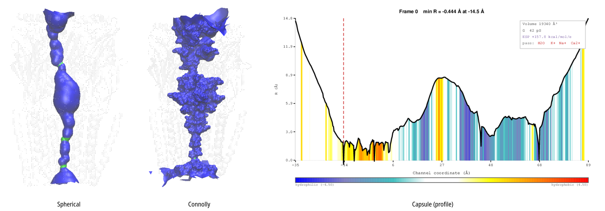
The default spherical method reports the radius of the largest sphere that fits without overlapping atomic van der Waals spheres. Two optional cross-section models are available:
- Connolly estimates the solvent-accessible cross-section and reports an equivalent radius. It requires the surface-processing stages and is sensitive to dot density. The Margin setting decides which dots count as the pore and which as lateral spill. Its lateral-opening tools are described below.
- Capsule fits an anisotropic stadium-like probe and reports its effective
radius. Use it when a circular radius hides a strongly elongated opening.
Its 3D surface is the union of the capsule slices, built by the same mesher
as the spherical surface, or by HOLE's own capsule pass in
sph_process(and its Tcl port) under the sos mesher; slices whose cap centres escaped past ENDRAD are dropped first, the rule HOLE's own profile applies. Centerline draws the two cap-centre tracks.
Keep the method fixed when comparing structures. Method names and equivalent radii are not interchangeable.
Surface smoothing. Settings can average the surface over neighbouring analysed frames, either following VMD's own trajectory-smoothing window of the shown representations or with a fixed half-width. It is a local average of the surfaces themselves, not of the atom coordinates and not of the centreline: a feature most frames share stays where it is, a flicker averages down, and curvature and lateral openings survive. The marching mesher averages the frames' distance fields on one grid and marches the mean; sos_triangle moves every dot of the frame to the mean of itself and its nearest same-facing dot in each window frame, then triangulates as usual (the pure-Tcl fallback does the same, byte for byte). Windows clamp at the trajectory ends, as VMD's do. The profile, the Mean Profile and every other number stay per frame. The lining and facing residues, and the property colours, follow the smoothed wall: they are tested against the spheres of every frame in the window.
The Search picker in HOLE Parameters chooses how each plane's sphere is
found: Monte Carlo (HOLE), HOLE's seeded simulated annealing, whose
steps, step size and kT fields appear only for it, or Nelder-Mead, a
deterministic downhill-simplex search in the nm_search engine that agrees
with HOLE to within HOLE's seed-to-seed spread. Without the engine the run
falls back to HOLE. Under Connolly, Nelder-Mead also builds the surface with
a port of HOLE's Connolly pass; for a Monte Carlo search, Settings chooses
between HOLE's conn and that port.
conn_lobes (Settings > Engines) classifies dots and colors lateral
openings; without it the same classification and coloring run in pure Tcl,
correct but a few seconds slower each time a new frame's coloring is built.
Inspect Connolly lateral openings
The isosurface and wireframe are meshed by mesh_csg (marching cubes on the
exact sphere union, Settings → Engines → Surface mesher). For a spherical run
the grid is 1.4 Å in the wide regions and 0.7 Å around the narrow pore; a
Connolly run uses 1.4 Å uniformly, since its whole surface is at probe scale.
Either way the same mesh is used while playing and once playback stops, so the
surface never changes shape as it settles: about 51 ms per newly visited frame
for a spherical run on a 200k-atom system and 63 ms for a Connolly one, with
the grid entry trading detail against that cost. Property colouring
recolours the same mesh.
After a Connolly run, draw an isosurface or wireframe and choose one of these Color modes:
pore_latseparates the traced pore from all surface regions that extend laterally beyond the selected Margin.pore_lobesseparates and tracks individual lateral openings. The region table appears below the graphics controls.
The table reports how often each opening is Seen, its neck radius and extension beyond the margin, and its axial and azimuthal location. Use each row to show, color, annotate, or export one opening; use the header gear for all regions. The matching controls and Seen floor are also in that gear.
For a two-dimensional view, choose Unrolled and Connolly reach. This
maps how far the Connolly surface extends from the centreline at each axial and
angular position, making lateral expansions easy to locate. These regions are
features of the Connolly pore surface, not independently calculated MOLE
tunnels. Tracking them across frames requires a fixed CPOINT and CVECT.
5. Run and validate
Select Run HOLE. The status line reports preparation, frame execution, and parsing. Abort requests cancellation of queued and running work; inspect the final status before using partial results.
Before interpreting a result:
- Display the centreline.
- Confirm that it remains inside the intended pore in representative frames.
- Check the terminal regions and the minimum-radius location.
- Review the VMD console for missing radii, failed frames, or executable errors.
- Keep the same effective seed when exact reproducibility is required; a blank
seed resolves to
1.
6. Use the analysis tabs
Pore Profile
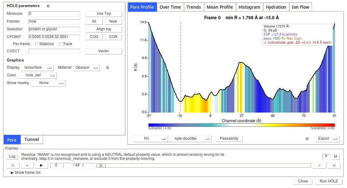
Shows radius against channel coordinate for the selected frame.
Property definitions, scale limits, and method citations are collected in Properties. The surface, Fill, and Mean Profile synchronize a property where it is available; Over Time has its own selector.
- None draws the profile only.
- Fill colors the profile by the selected property.
- Ellipse fit shows the fitted non-circular cross-section as a solid surface or point cloud.
- Unrolled maps the cylindrical pore wall into axial and angular coordinates. Choose structural or physicochemical layers; see Properties.
Swap and flip controls change presentation only. Export the figure and its CSV from the same tab.
Over Time
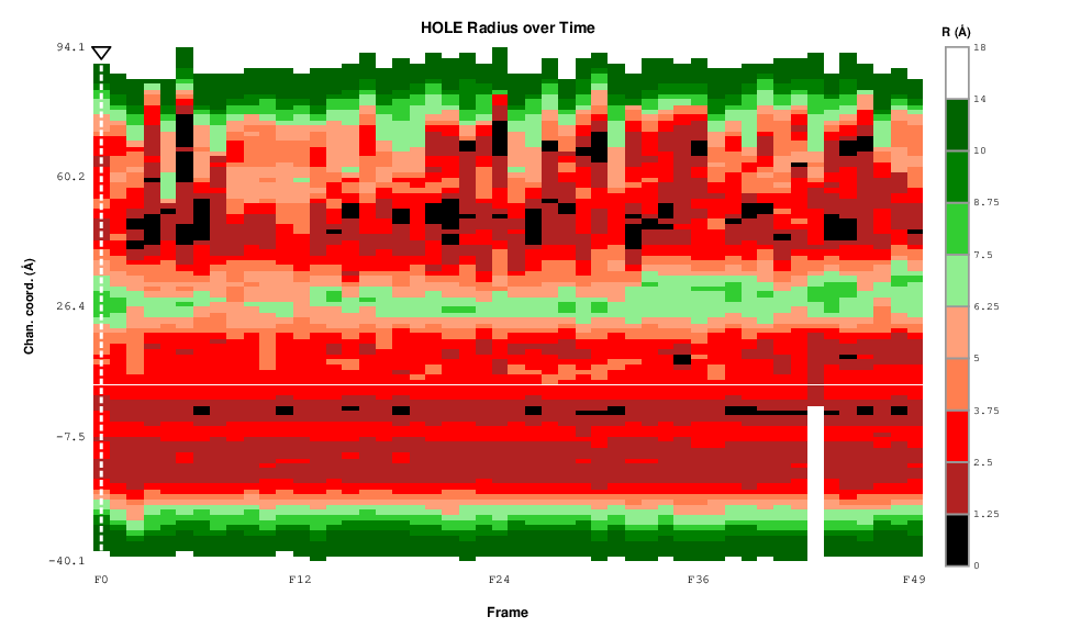
Shows position by frame for either radius or a selected property. Radius can come from the HOLE profile or the ellipse fit. The property selector is independent of the shared 3D/Profile/Mean selector.
An expensive property or ellipse calculation is not launched implicitly. Select Compute when the tab reports that its cache is stale. Record the chosen source and color scheme with exported data.
Mean Profile
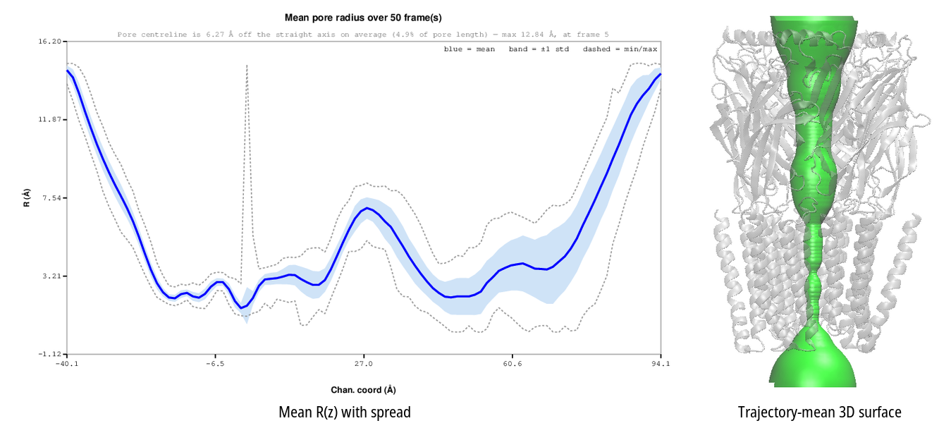
Aggregates compatible profiles across analysed frames and reports their spread. Optional controls add a property fill or a revolved 3D mean surface. The accurate 3D property projection and large frame caps increase cost.
Mean Profile pools radius samples into fixed axial bins. A constriction that moves along the axis can therefore appear wider or more diffuse. Use Trends with Min R and the Over Time map to inspect mobile constrictions.
Trends
Plots one value per frame. Pore-mode metrics are minimum radius, ellipse minimum radius, pore volume, ellipse volume, HOLE-derived conductance, ellipse-area conductance, confinement-corrected ellipse conductance, and average electrostatic potential when available. Conductance is a geometry-based estimate and depends on the selected bulk conductivity.
The gear also controls the residue shell used by the bottleneck-residue report.
Histogram (radius summary)
Summarizes radii along the channel in 50 axial bins. Choose the mean, minimum, or maximum radius. The bars report position, not a probability distribution. To keep the plot readable, unusually tall terminal bars can be visually truncated and marked; CSV values are unchanged.
Hydration
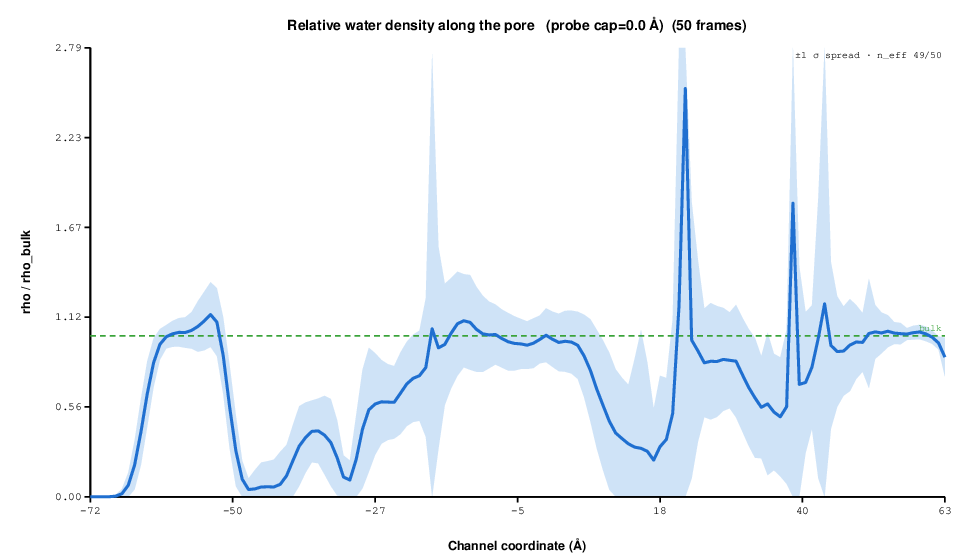
Hydration is CHAP-compatible pore analysis for explicit-water trajectories. Set a VMD water-oxygen selection and select Compute. Views are Density, Energy, Hydrophobicity, and Per-frame ρ. Use a prepared, adequately sampled trajectory; do not use hydration results from a dry structure or implicit-solvent model. CHAP mode uses CHAP-compatible settings and tracked per-frame geometry. Cite CHAP from the reference list.
Ion & Water
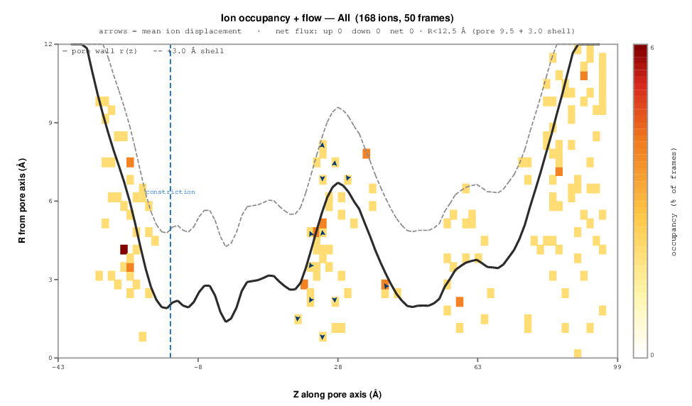
Requires ions or water and at least two trajectory frames. Occupancy + flow maps where the chosen species is observed in the pore coordinate system; its header reports the net flux through the lumen, counted from constriction crossings inside the lumen radius.
Passage draws the path of every molecule that entered the pore against frame number, in the species colour, faded when there are more than a few hundred paths. For water, stretches that cross the constriction are drawn last in their direction's colour (red up, blue down, purple for crossed and returned).
Count vs frame plots how many molecules are inside the pore at each frame, one curve per ion type when all types are selected. The y axis starts at zero unless the counts stay well above it.
The Species menu lists every ion type detected plus Water. All is
the ion types only. Water counts one oxygen per molecule from the
Hydration tab's water selection against the same per-frame pore geometry; it
is scanned the first time it is picked (about 2.5 s for 100 frames of a
200k-atom system with the fast sos_triangle) and cached after that. For
water the Passage view has a Show picker: All crossing (default),
Passage up, Passage down, or All entered, which also draws the
molecules that never crossed.
None of these views is a full permeation count. Select Permeation to count complete bulk-to-bulk crossings along the per-frame pore axis. Supply bulk planes, the saved-frame interval, and an applied voltage only if they are physically defined. VMDHole warns for coarse sampling, wrapped protein coordinates, and non-orthorhombic cells; re-image or treat such counts as unvalidated.
Passability and bottleneck residues
Passability compares the minimum radius with tabulated bare and hydrated species radii and reports geometry-based conductance metrics. It does not model dehydration barriers, electrostatics, or binding.
The bottleneck-residue dialog reports residues within a surface-distance shell of the minimum-radius sphere and exports the table. This shell is independent of the property-lining cutoff.
7. Save, import, and report
Use File → Import to restore a saved pore or tunnel run. Exported figures should be accompanied by CSV data and the run parameters listed in the parameter reference.
Citations
For a publication, cite VMDHole, VMD, and HOLE. Add the method citation for the features used, such as hydration, property scales, ellipse analysis, Connolly surfaces, or conductance estimates. Use Help → Guide & Citations… → Citations in the plugin or the reference list.