Tunnel workflow
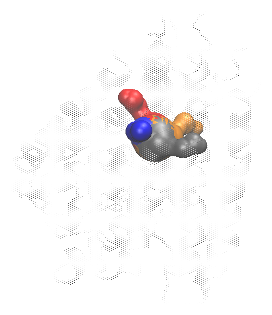
Tunnel mode searches for routes from a buried site to the molecular surface. Use it for internal cavities, enzyme access paths, and branched egress routes. Use pore mode instead when one known channel axis is the object of study.
For a publication using Tunnel mode, cite MOLE 2. If route clustering is used, also cite CAVER 3.0; both references are listed in References.
1. Prepare and align
Load the structure or trajectory and choose the atoms that define the molecular interior. Make periodic structures whole before analysis. For trajectory-wide route tracking, Align trajectory is on by default. Keep it enabled and choose a stable reference selection unless the trajectory is already aligned. It fits the loaded frames before searching. Cross-frame clustering compares route geometry; translation or rotation of an unaligned protein is otherwise interpreted as route motion.
2. Define the origin
The start point should lie in the buried cavity of interest. Enter coordinates, use a selection's centre of geometry (COG) or VMD's centre of rotation (COR), or enable automatic origin detection. A poor origin can return no routes or routes from the wrong cavity. The ⌖ button opens the on-screen stick described under pore mode, step 3, to nudge the start point relative to the current view.
Custom exits restrict the search toward known surface regions. A custom path is defined by start and end points. Use custom exits only excludes other exit candidates; use it only when the biological exit is independently known.
3. Set the search criteria
The six controls shown in the main panel are sufficient for most analyses:
| Control | Default | Meaning |
|---|---|---|
| Probe | 3.0 Å | Probe used to define accessible void space |
| Interior | 1.25 Å | Minimum interior clearance |
| Origin radius | 5.0 Å | Region around the requested start used to seed origins |
| Minimum length | 0 Å | Reject routes shorter than this value |
| Bottleneck | 1.25 Å | Minimum accepted route radius |
| Cluster within frame | on | Merge geometrically similar routes in each frame |
The remaining search, exit, clustering, and rendering controls are available from the ⚙ next to MOLE parameters. They are defined in the parameter reference. Change one class of parameters at a time and retain the settings with exported results.
4. Run and inspect routes
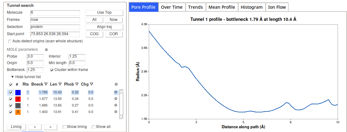
Select Run Tunnel. The route table reports:
| Column | Meaning |
|---|---|
| Show | Visibility |
| route/color | Tracked route identifier and display color |
| Rts | Number of route instances represented by the cluster |
| Bneck | Mean bottleneck radius |
| Len | Mean route length |
| Phob | MOLE length-weighted hydrophobicity mean |
| Chg | Mean net formal charge |
| Seen | Percentage of analysed frames containing the tracked route |
Sort by a column to inspect a different property; sorting does not alter route identity. Expand a row for details. The row gear controls that route's representation, color, material, and property. The global gear applies display choices to routes without a per-route override.
Route surfaces are meshed by mesh_csg (Settings → Engines → Spherical
mesher), the same marching-cubes mesher the spherical pore uses, since a
route is a union of spheres along its centre line. A route coloured by a
property is meshed by sos_triangle instead, because the per-triangle
recolouring reads that program's own mesh records. On a four-route frame of
KcsA, meshing and drawing took 59 ms against 217 ms for sos_triangle.
Tunnel properties are Kyte–Doolittle, Wimley–White, Kapcha–Rossky, Fauchère–Pliska, and the MOLE hydropathy, hydrophobicity, polarity, charge, ionizable, logP, logD, logS, and mutability fields. See Properties for their definitions and citations.
First validate every candidate in 3D. A high-ranked route can still be an irrelevant solvent-accessible groove, and a route that terminates incorrectly usually indicates an origin, selection, exit, or interior-classification issue.
5. Cluster and track
Cluster within frame merges similar candidates produced in one structure. The bottleneck-row clustering control sets its geometric cutoff.
Cross-frame clustering assigns a persistent route identity to matching routes from aligned frames. It is controlled by maximum geometric deviation, maximum ranks considered per frame, and the minimum Seen percentage. Restricting ranks reduces cost but can hide a route that is poorly ranked in some frames.
Treat a low-Seen cluster cautiously in Mean Profile or trend plots: the average may describe only a small subset of frames. Cross-frame identity is a geometric classification, not proof that individual solvent molecules use the route.
6. Display lining residues
Select a route and open Lining to inspect protein residues and HET groups in contact with it. Show lining creates a VMD representation; previous/next controls step through routes. Show all displays the routes that remain after the current filters.
The lining window exports the selected route's lining data. The standard plot tabs and CSV exports operate on the selected tracked route.
7. Available downstream analyses
Tunnel mode supports the radius/profile, Over Time, Mean Profile, Trends, Histogram, property, lining, and Ion & Water views. Ion & Water measures the selected route along itself, as distance along the route and distance from it, so a bent tunnel plots as it is. It does not provide tunnel hydration, tunnel ellipse fitting, or pore-mode bulk-to-bulk permeation. Water free-energy and density properties require a pore-mode hydration result.